


**The Importance of Proper Design and Production of Electrical Panels for Compression Chillers**
The proper design and production of the electrical panel for a compression chiller play a crucial role in the correct and long-term operation of the chiller. Essentially, the electrical panel manages the chiller’s performance. The panel contains numerous and varied components, but these can generally be classified into two main sections:
1. **Power Circuit Components**: These components are responsible for distributing the required electrical power to each of the chiller’s consumers. Some of these components include:
– **Main Switch**: The power needed for the chiller, with a frequency of 50 Hz (in Iran) and a voltage of 380 to 400 volts, which is usually three-phase, is connected to the main switch of the electrical panel. Therefore, the main switch serves as the primary power supply for the electrical panel. 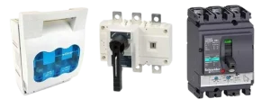
Types of Main Switches in Chiller Electrical Panels
**Busbars:**
Busbars are responsible for distributing and dividing electrical current from the main switch to the various consumers within the system. They are made from copper bars. Essentially, a busbar is an electrical conductor that acts as a common connection point for two or more circuits. Busbars must be installed in the electrical panel in such a way that they are protected from physical damage and securely fixed in place. 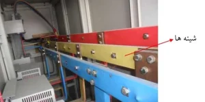
Busbars in Chiller Electrical Panels
The compressors are arguably the primary and most significant consumers of electrical power in a compression chiller. Therefore, protecting them against overloads and short circuits is of utmost importance. To achieve this, specialized switches are used at the beginning of the power circuit for each compressor. These switches provide both magnetic and thermal protection. 
Types of Main Switches for Compressors in Compression Chillers
**Compressor Contactor:**
A contactor is a type of magnetic switch that serves as the link between the control circuit and the power circuit. This means that when the PLC sends a signal to turn on the compressor, it is the contactor that permits the electrical current to flow to the compressor. Since contactors cannot provide protection against overloads and short circuits, they should be installed after the compressor’s main switch. 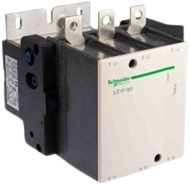
Compressor Contactor:
This component is always installed after each contactor. As its name suggests, it provides thermal protection for the compressor. The bimetal thermal relay monitors the temperature and disconnects the power if the compressor overheats, protecting it from damage due to excessive heat. 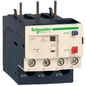
Compressor Thermal Relay:
**Thermal Magnetic Switch and Contactor for Condenser Fans:**
In the electrical circuit for the air-cooled condenser fans (in air-cooled compression chillers), each fan is equipped with a thermal magnetic switch (MPCB) and a contactor. 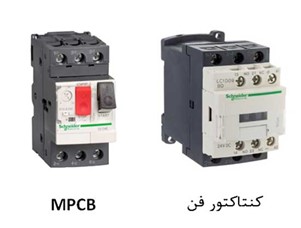
Contactor and Thermal Magnetic Switch in Air-Cooled Compression Chillers
**Control Circuit:**
The control circuit manages the operation of the chiller’s main components, including the compressor and the air-cooled condenser fans.
**Controller (PLC):** PLC stands for Programmable Logic Controller. It is an industrial digital computer used for controlling manufacturing processes, robotic devices, or any activity requiring high reliability. In a compression chiller, the PLC issues control commands to the compressors, air-cooled condenser fans, and other actuators based on parameters measured by sensors and programming done by the manufacturer. Therefore, the PLC plays a crucial and special role in the chiller’s operation. 
PLC in a Compression Chiller
**The Importance of Proper PLC Programming for Chillers**
Proper programming of the PLC (Programmable Logic Controller) is crucial for the correct operation of the chiller and ensures that its performance aligns with the project requirements. The PLC programming allows the chiller to be operated in a manner that meets the specific conditions of the project. 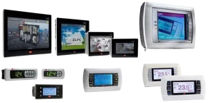
**PLC Display (HMI):
HMI stands for Human-Machine Interface. It is a display that shows the signals received by the PLC, allowing the operator to monitor the chiller’s performance. Additionally, the operator can adjust certain set points within the allowed range. This is why it is called HMI, meaning the interface between human and machine.
The level of access for the operator to control items must be defined. For example, an operator who has only undergone basic operational training should not have the same level of access to change set points as a technical expert from the manufacturer. The design of the HMI ensures that only authorized personnel can make significant changes, preventing unauthorized modifications and ensuring the proper functioning of the chiller. Author: Eng. Amirali Ghiassvand